Data Logger Settings
In the Data Logger view, click  to configure the data logging settings and enable phase alert status.
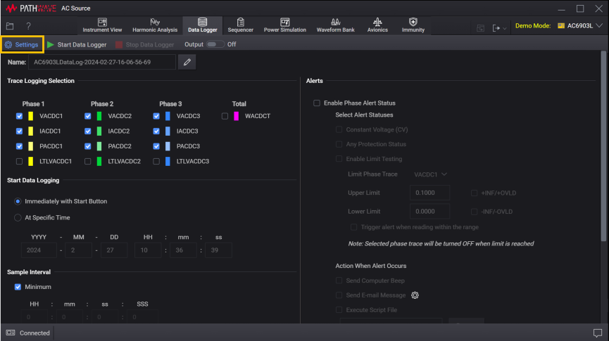
Data Log Name
The default file name consists of the AC Source model number followed by "DataLog", the date, current time, and a numeric index. For example, AC6906HDataLog-2021-11-20-11-40-26-31.
For example – C:\Users\<user_name>\Documents\Keysight\PathWaveACSource\Data Logs\.
To change the default name, click ![]() to open the file name editor. You can edit the prefix name and also have the option to include or exclude the date, current time, and numeric index. The date is in the form YYYY-MM-DD and the time is in the form HH-mm-ss (24-hour time format). For example, <model>DataLog-2021-11-20 11-40-26-31 – November 20, 2021 at 11:40:26AM with a numeric index of 31.
to open the file name editor. You can edit the prefix name and also have the option to include or exclude the date, current time, and numeric index. The date is in the form YYYY-MM-DD and the time is in the form HH-mm-ss (24-hour time format). For example, <model>DataLog-2021-11-20 11-40-26-31 – November 20, 2021 at 11:40:26AM with a numeric index of 31.
- If included, the date, time, and numeric index fields are automatically updated with each subsequent data log operation from this application.
- The date and time fields are based on your computer's internal clock setting.
- The data log is stored with an *ivif file extension.
Trace Logging Selection
Select data logging traces. You can select data logging for individual phase and total measurements for all phases.
- VACDC – Voltage for ACDC
- IACDC – Current for ACDC
- PACDC – Power for ACDC
- LTLVACDC – Line-to-line ACDC voltage
- WACDCT – Total power for ACDC
The number denotes the respective phase number.
Start Data Logging
Immediately with Start Button – Start data logging when you click the Start Data Logger button.
At Specific Time – Start data logging at a specific time and date. Enter the desired date in the form YYYY (year), MM (month), and DD (day). Enter the desired time in the form HH (hours), mm (minutes), and ss (seconds).
Sample Interval
Enter the desired interval between samples in the form HH (hours), mm (minutes), ss (seconds), and SSS (milliseconds). Select Minimum to select the shortest interval based on the instrument's current settings.
Stop Data Logging
Immediately with Stop Button – Terminate data logging when you click the Stop Data Logger button.
After Elapsed Time – Terminate data logging after the specified amount of time has elapsed. Enter the desired duration in the form DD (days), HH (hours), mm (minutes), and ss (seconds).
After number of samples acquired – Terminate data logging after a specific number of samples have been taken (the minimum number of samples is 2).
Alerts
- Select Enable Phase Alert Status to enable the alerts.
- Select the status conditions that generate an alert when the condition is reached. Available conditions are:
- Constant Voltage (CV)
- Any Protection Status
- Enable Limit Testing
- Select the actions when alert occurs.
- Send Computer Beep – The computer and the instrument beep on each limit failure.
- Send E-mail Message – Send an e-mail to the specified recipient upon the first limit failure (multiple failures per test result in just one e-mail) only. Click
 to specify the e-mail recipient.
 - Execute Script File – Execute a custom script file upon the first limit failure only. Click Browse to locate and select the custom script file that you have created.
Enable Limit Testing
Check readings against upper and lower limits. A limit failure occurs when the measured signal goes above the upper limit, or below the lower limit.
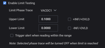
Limit Phase Trace – Select the phase trace that you want to set the conditions.
Upper Limit – Specify the upper limit in the units of the selected measurement (must be greater than the lower limit). Check +INF/+OVLD to set the limit to infinity or overload reading.
Lower Limit – Specify the lower limit in the units of the selected measurement (must be less than the upper limit). Check -INF/-OVLD to set the limit to infinity or overload reading.
Check Trigger alert when reading within the range to enable alert for reading within the upper and lower limits.